
TTU Telecom Review Process for Integrator Installed Systems
(v2.1 2021-05-18)
The following information and requirements apply to any work carried out at TTU locations that involves network cabling or digital communications as part of an integrator installed system:
Step-by-Step Process
- Determine system category (see Categories and Requirements below).
- Prepare system integrator's installation plan. To speed review, include connection diagram.
- Submit TTU Telecom Network Service Request with details and integrator's installation plan.
- Review system details with TTU Telecom.
- Upon approval by TTU Telecom, system installation work may commence.
Definitions
- Cable, Cables, or Cabling: Any UTP, STP or fiber-optic cabling used for digital networking (e.g., Ethernet, HDBaseT, AVB, Dante, Audio over Ethernet, etc.).
- Facility Cable Plant: The permanent building infrastructure for data communications. Includes main- and intermediate-distribution facilities (comm rooms), racks, patch panels, raceways, chases, faceplates, cables and any related equipment or mounts.
- Integrator: An organization which designs, installs, maintains, and supports a specialized multi-component system. Typically, these systems include environmental, security, audio/video, or media related applications.
- Integrator System: The system installed by an Integrator.
- Integrator LAN: Integrator-managed layer 2 Ethernet network containing only the Integrator System components.
- Building LAN: TTU-managed layer 2 Ethernet network within the building for communications within the building and TTU intranet. This LAN is generally the building's A/V LAN which is dedicated to A/V equipment and has access to communicate with other systems on campus. If granted exceptions by TTU Security, this LAN can also access Internet-based resources.
- Isolated Room Installation: Cabling within a single room, with network communications only within the Integrator LAN.
- Building Cable Installation: Cabling spans beyond a single room, with network communications only within the Integrator LAN. Facility Cable Plant is used to span rooms.
- Building Network Installation: Communications largely fit the definition of either an Isolated Room or Building Cable Installation, but some communication with the Building LAN is required for broader control, media transmission or system monitoring.
- TTU Telecom Network Service Request: Online submittal form for requesting the involvement of TTU Telecommunications in the review or installation of an Integrator System. Online form located at https://www.net.ttu.edu/.
Categories and Requirements
Integrator Systems fall into several generalized categories. Consider which of these categories fits your situation and include that category in any submitted information.
Isolated Room Installation
- Integrator System only connects and communicates between components in the Integrator LAN and those components do not communicate with other devices beyond the Integrator LAN (i.e., a closed system).
- No cable interconnections exist with the Facility Cable Plant infrastructure or the University-managed network equipment.
- Integrator LAN equipment must only include wired layer-2 switch equipment (no Wi-Fi equipment is permitted).
- IP addressing within the Integrator LAN is the responsibility of the system integrator.
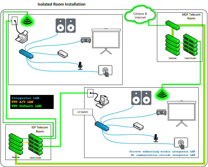
Overall Structure:
- The top section illustrates one room's installation connecting to a "MDF Telecom Room" and then to "Campus & Internet."
- The bottom section illustrates a second, identical room's installation connecting to an "IDF Telecom Room" and an "Integrator LAN."
- All main network connections are shown in green, while AV/device connections within the room are blue.
Detailed Room Configuration (Identical for both rooms):
Each room contains the following equipment connected by blue lines, indicating AV/device connections:
- Projector Screen: Paired with a projector for visual display.
- Speakers: For audio output.
- Control Panel / Touch Screen: For user interaction and system control.
- Microphone: For audio input.
- Small Form Factor PC / Media Player: A source device.
- Network Switch (Small): A central hub within the room, connecting most of the AV and control devices.
- Wireless Access Point (WAP): Depicted with a glowing green icon, providing wireless connectivity within the room. This WAP also has a power connection.
- Printer: Connected to the room's network switch.
External Connectivity:
The top room connects to the MDF Telecom Room and the wider Campus & Internet. The bottom room connects to the IDF Telecom Room and a segmented "Integrator LAN" with private addressing, indicating no communication outside its own LAN.
Building Cable Installation
- Integrator System communicates between components within the Integrator LAN beyond a single room.
- Any cabling spanning rooms must make use of the Facility Cable Plant.
- Any cabling not spanning rooms must adhere to Isolated Room Installation requirements.
- Facility Cable Plant installation must be carried out by TTU Telecom in conjunction with a TTU Telecom Network Service Request.
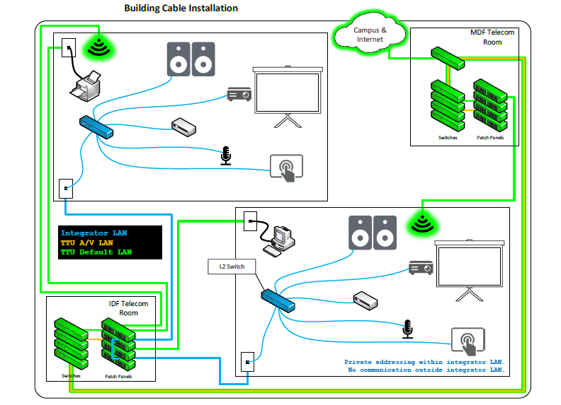
Overall Structure:
This "Building Cable Installation" diagram shows two rooms with identical AV equipment, but with a different network wiring strategy than the "Isolated Room" example. Here, connectivity is centralized through the MDF and IDF Telecom Rooms.
In-Room Equipment (Identical for both rooms):
Each room contains a projector, speakers, control panel, microphone, PC/media player, a local network switch, and a Wireless Access Point (WAP).
Network and Data Connectivity (Green Lines):
- The WAPs and printers in both rooms connect via green lines to the MDF Telecom Room.
- The MDF Telecom Room then provides a shared connection to the "Campus and Internet."
AV Connectivity (Blue Lines):
- The local AV network switch in both rooms connects via a blue line to a wall plate.
- These blue-line connections are both routed to patch panels within the IDF Telecom Room.
- The IDF Telecom Room also connects to an "Integrator LAN," which is noted as having private addressing and "No communication outside integrator LAN," indicating a segmented, secure network for the AV equipment.
Building Network Installation
- Pertains to an Integrator System which communicates with the Building LAN.
- The Integrator System must provide layer 3 routing between the Integrator LAN and the Building LAN (i.e., the Integrator LAN may not bridge or switch to the Building LAN).
- The Integrator System must use port address translation (PAT) in order to communicate between the Integrator LAN and the TTU Building LAN.
- IP addressing within the Integrator LAN is the responsibility of the integrator.
- Building LAN must not be impacted by any Integrator LAN service (e.g., DHCP).
- IP addressing within the Building LAN is the responsibility of TTU and handled exclusively by DHCP (i.e., no manual IP configurations for integrator equipment in the Building LAN).
- Coordination of Building LAN communication must be carried out by TTU Telecommunications in conjunction with a TTU Telecom Network Service Request.
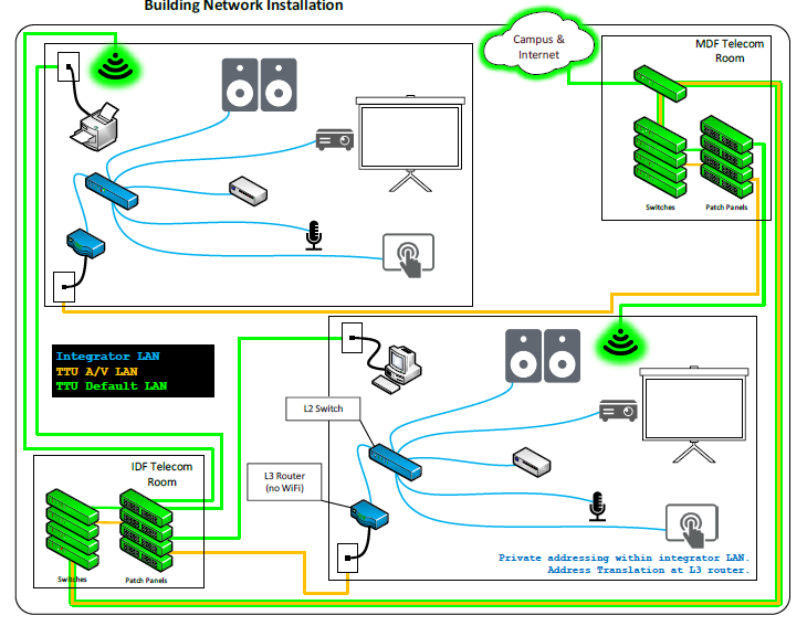
Overall Structure:
This "Building Network Installation" diagram introduces a more complex routing setup, distinguished by an L3 Router and new orange connection lines. The design facilitates Network Address Translation (NAT) for enhanced network segmentation.
In-Room Equipment:
The AV equipment in each room (projector, speakers, microphone, etc.) remains consistent with previous diagrams.
Connectivity Details:
This diagram uses three colors to represent different network connection types:
- Green Lines (Default Network): In both rooms, the Wireless Access Point (WAP) and printer connect via green lines to the MDF Telecom Room, which provides access to the "Campus and Internet."
- Blue Lines (Local AV Network): These lines connect the local AV devices within each room to their respective local network switch.
- Orange Lines (Routed/Translated Network):
- In the top room, the local AV switch connects via an orange line to the MDF Telecom Room.
- In the bottom room, the local AV switch connects to an in-room "L3 Router." This router then connects via an orange line to the IDF Telecom Room.
An annotation in the bottom room clarifies the setup: "Private addressing within integrator LAN. Address Translation at L3 router." This indicates the L3 router is isolating the room's private AV network from the broader network while managing traffic between them.
Network Services | Unified Comm, Auth & Cloud
-
Address
Texas Tech University, 2500 Broadway, Lubbock, TX 79409 -
Phone
806.742.8000